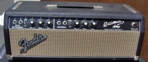
This is the second installment in the series of modifying a Fender Bassman amp with an AB165 circuit back to the more desireable AA864 (Leo Fender circuit).
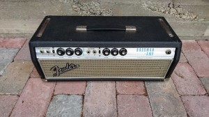
These mods can also be applied to a huge amount of silverface ‘transitional’ amps. The AB165 circuit was utilized in these amps until 1970. For the most part, this mod and the bias adjust mod are the bulk of what’s necessary to ‘blackface’ an AB165 circuit.
DO NOT MODIFY A RARE LEO FENDER AA864 CIRCUIT!! ALSO, DO NOT ATTEMPT TO WORK ON THESE AMPS UNLESS YOU KNOW WHAT YOU ARE DOING, AS THEY CONTAIN VOLTAGES THAT ARE LETHAL AND WILL KILL YOU!!!
This mod will focus on the absolutely horrible negative feedback loop that CBS added. We will be removing it for the most part, restoring it back to AA864 specs. We will also be discussing how we can tweek the frequency of the sound as well.
Let’s start off by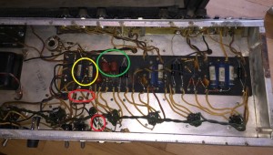 taking a look at Jim’s 1966 AB165 Bassman for the areas we will be concerned with. Marked in red are the main areas of the NFB loop. Marked in yellow are the coupling caps from the phase inverter stage to the power tubes. Marked in green is the part of the feedback that we will leave, but possibly tweek a little bit. Why remove the power tubes’ NFB, you ask? Because the end result of the NFB are a ‘neutered’ sound as well as lower volume and a ‘sweet spot’ of tube breakup at a higher volume setting. So, by removing it, you will get: more volume at a given setting and the tubes will break up at a lower volume setting. (You will get a little more white noise, but this should be able to be minimized by ‘adjusting’ the area in green a little bit.)
Here, we see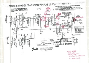 a copy of the AB165 schematic that I marked up with the changes. (Don’t forget that you can click on it to see it full size.) First thing is to remove the two 220K feedback resistors as well as to swap the two wires going to the speaker outputs and the feedback loop that is going to remain. The two coupling caps from the phase inverter stage to the power tubes will be changed from .022 back to the AA864 values (.1). Also, change the .1 coupling cap (from the output of the gain stage to the input of the PI) to the value used in the AA864 circuit, 500pf. Also, in order to put the feedback loops back to Leo Fender specs, you need to replace the 47K resistor with an 820 Ohm one as well as remove the .1 cap (with the square around it). You also need to move the feedback loop solder point to the 22K resistor. This point is currently at ground, so you need to insert a 100 Ohm resistor to ground.
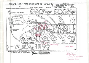
Here is the layout diagram for the NFB mod. The cap (with the square around it) can be either taken out (to restore the loop to Leo Fender specs), or left in, or changed to a different value (to change the frequency response of the feedback). For example, going to a .01 cap only allows the higher frequencies to pass (and cancel), getting rid of the harshness. You can also change the 820 Ohm resistor to 1.5 K Ohm, reducing the amount of feedback felt, and allowing for a better tube breakup.
If you think this through carefully, you can make the cap ‘switchable’ using the ground switch, if you have bypassed it and removed the ‘death cap’. Or, you could utilize the 1/4″ Ext Speaker jack (if you disconnect it), and make the cap and/or resistor switchable via a latching foot switch.
That conclude this segment. This mod might not be for you if you want a calmer, mellower Bassman. This mod might be for you if you want an aggressive Bassman with more bite and more volume and better break up at lower volumes, and the ability to ‘cut through’ the music. 😉
Next segment will look at tone shaping.
