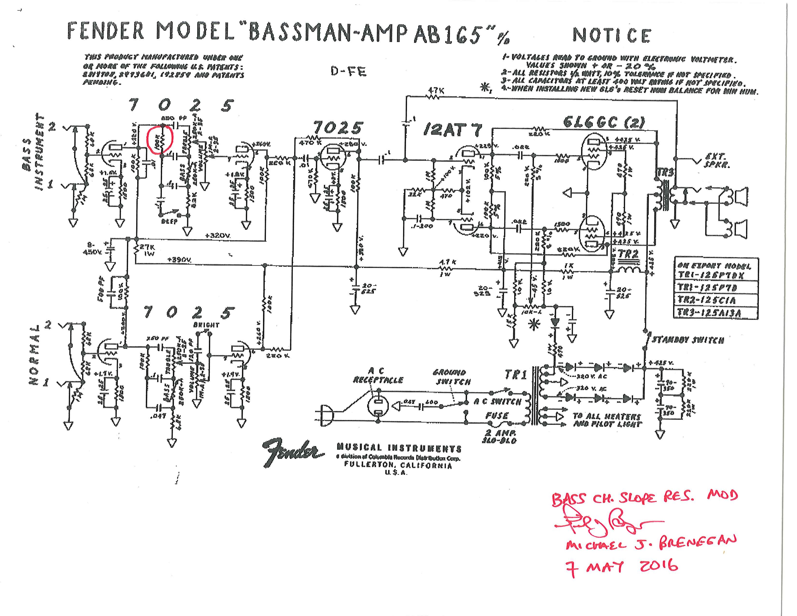
This mod is the preface to putting in a switchable slope resistor for the bass channel. First, unless you want to drill a hole to mount a switch, you may as well use the unneeded ‘ground switch’. Also, if your amp still has the death cap, it will have to go, as well. 😉 You will need two 8 inch lengths of cloth covered stranded wire, if you wish to stay ‘period specific’. Otherwise, you can use regular stranded wire, if that doesn’t concern you. (I would keep the wire that you remove in case you wish to revert….) THIS LINK, Angela, has everything you might need, from cloth covered wire, to caps, or whatever. So, besides the two 8 inch lengths of wire, you will need basic soldering skills.
And MAKE SURE that you discharge the caps, and verify it (like the video below) and UNPLUG the amp, since you will be working on the AC mains.
DO NOT MODIFY A RARE LEO FENDER AA864 CIRCUIT!! ALSO, DO NOT ATTEMPT TO WORK ON THESE AMPS UNLESS YOU KNOW WHAT YOU ARE DOING, AS THEY CONTAIN VOLTAGES THAT ARE LETHAL AND WILL KILL YOU!!!
That being said, here’s a great video showing you how absolutely easy it is to discharge the filter caps in a tube amp. This is how I’ve done it my whole life. Remember, when in doubt, measure the B+ with a DMM!
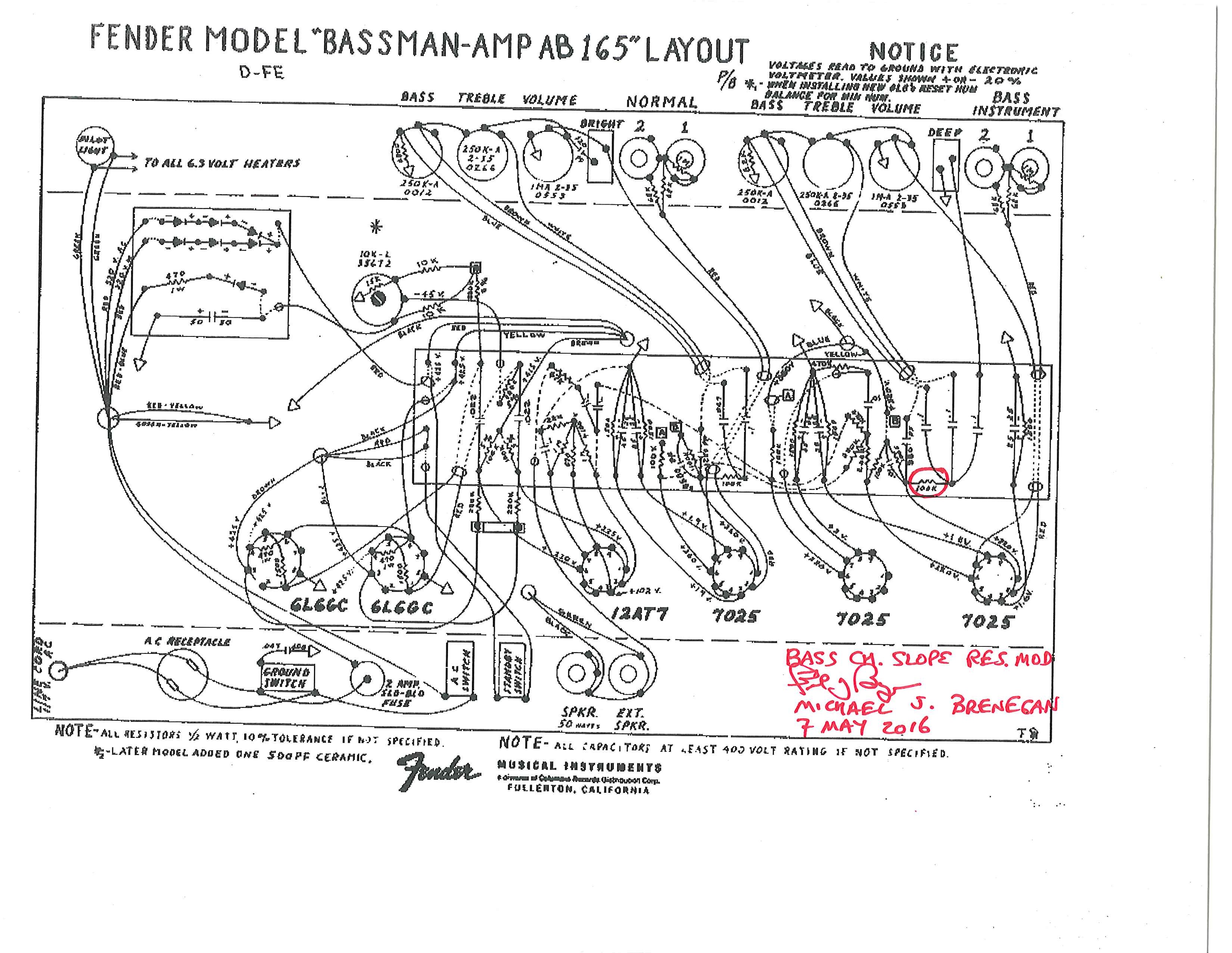
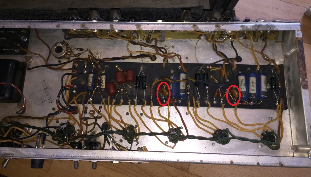
In the picture at the right, you will notice the area that we will be concerned with, 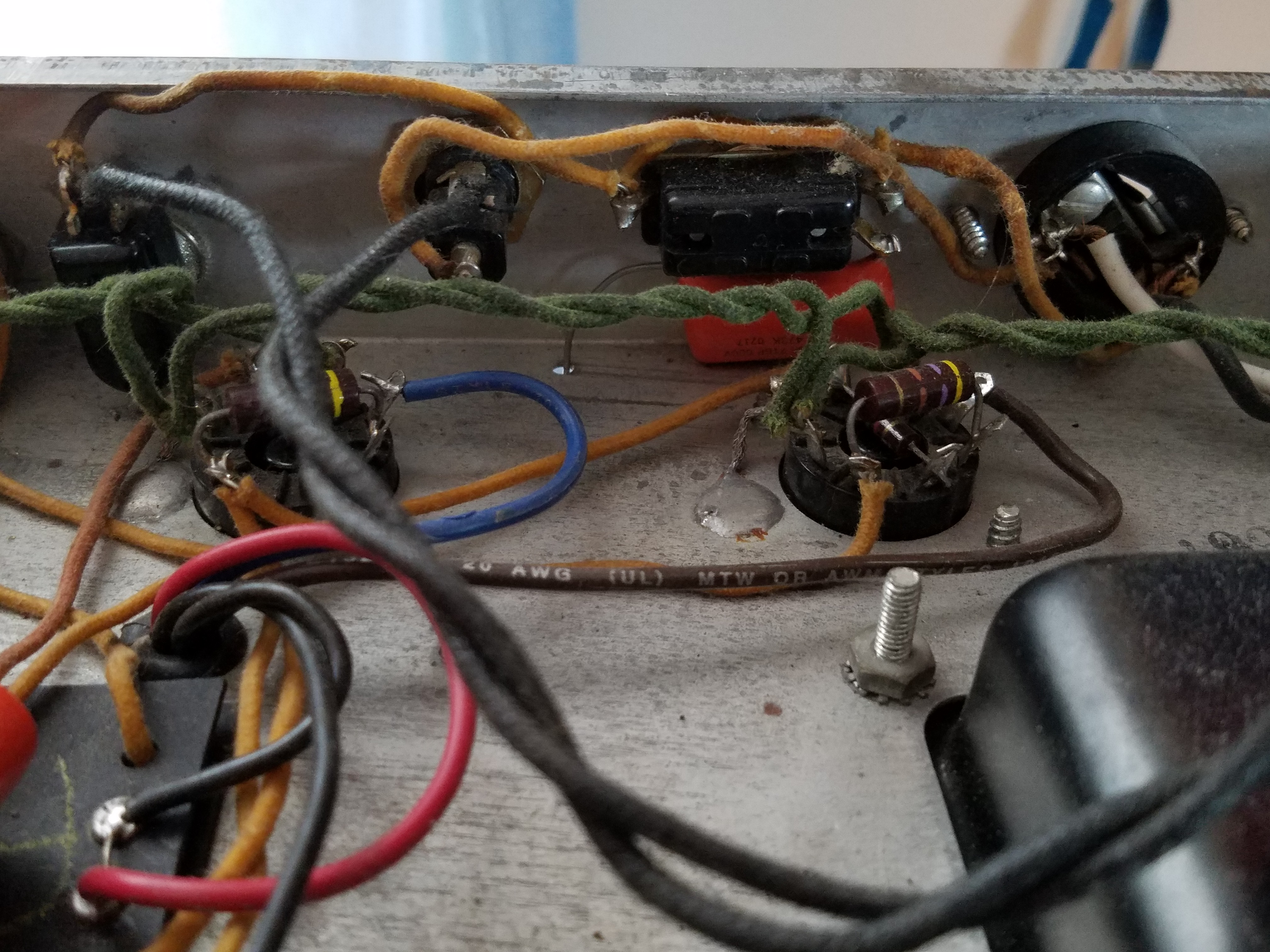 and should be fairly common across the different Bassman circuits: AA864, AA165, AB165…. You will notice on the right, that this amp has had the power cord replaced, and connected the hot and neutral wires to the two wire socket. These wires are daisy chained across the ground switch before reaching the power switch and fuse holder.
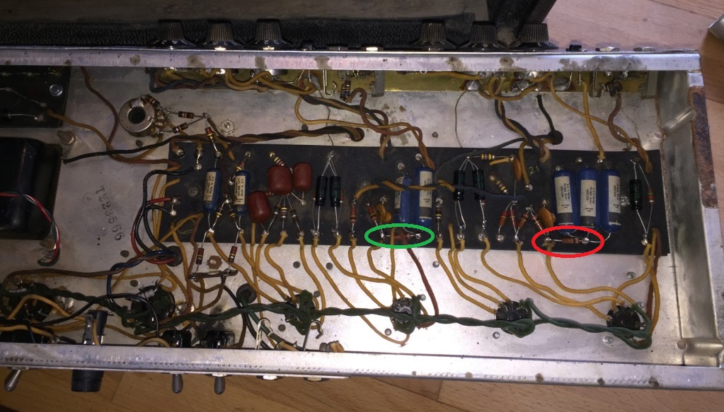
 First, we will remove the two small lengths of cloth covered wire connecting the black wire to the ground switch and the fuse holder. As you can see in the picture to the left, I have removed those two wires from the terminals marked by the red arrows.
Next,we will remove the two small lengths of cloth covered wire connecting 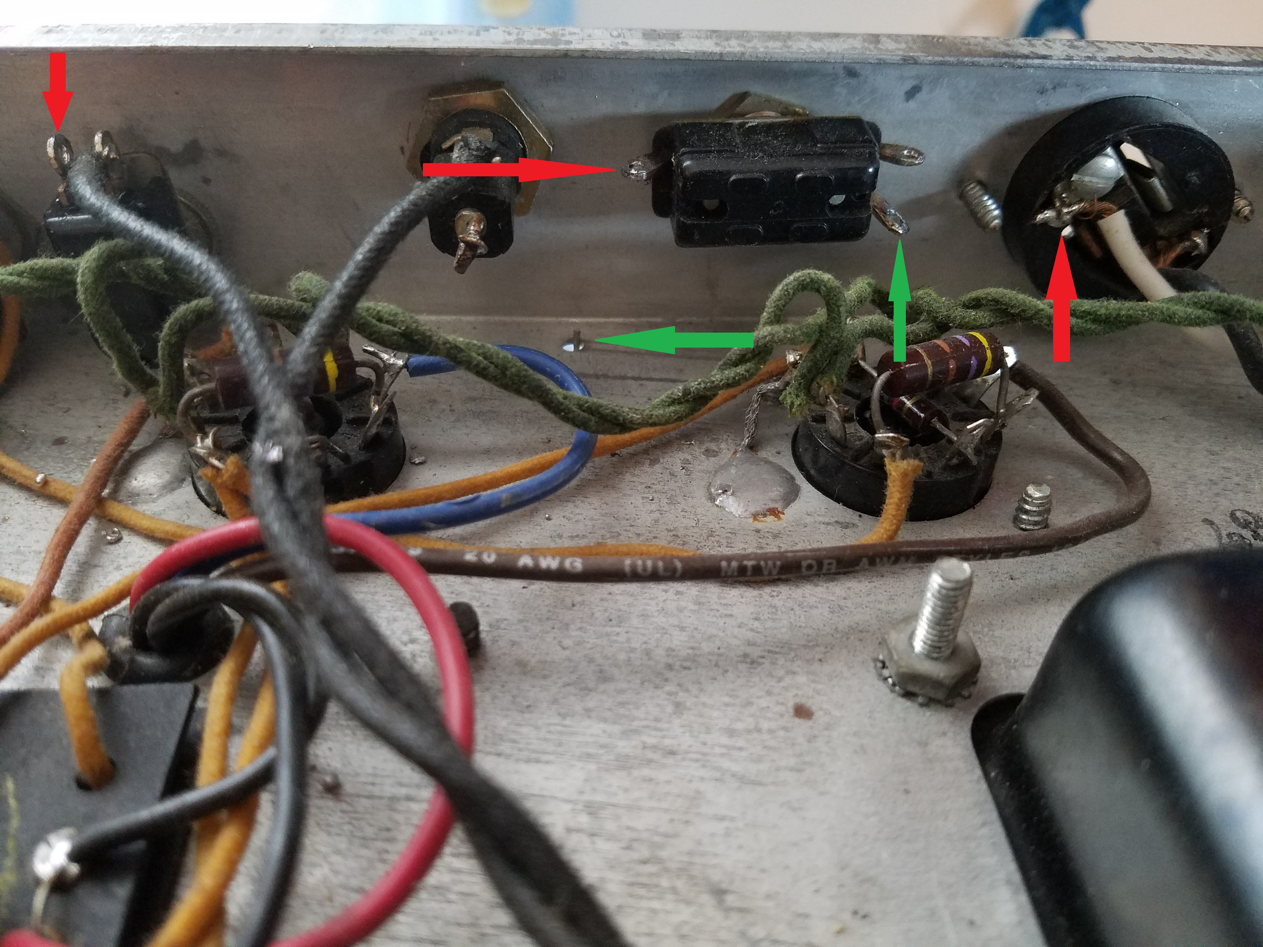 the white wire to the ground switch as well as the main power switch. As you can see in the picture at the right, the points that I removed those wires from marked by red arrows. You will also notice that the ‘death cap’ has been removed, as marked by the two green arrows. (I actually just snipped off the lead going through the hole.)
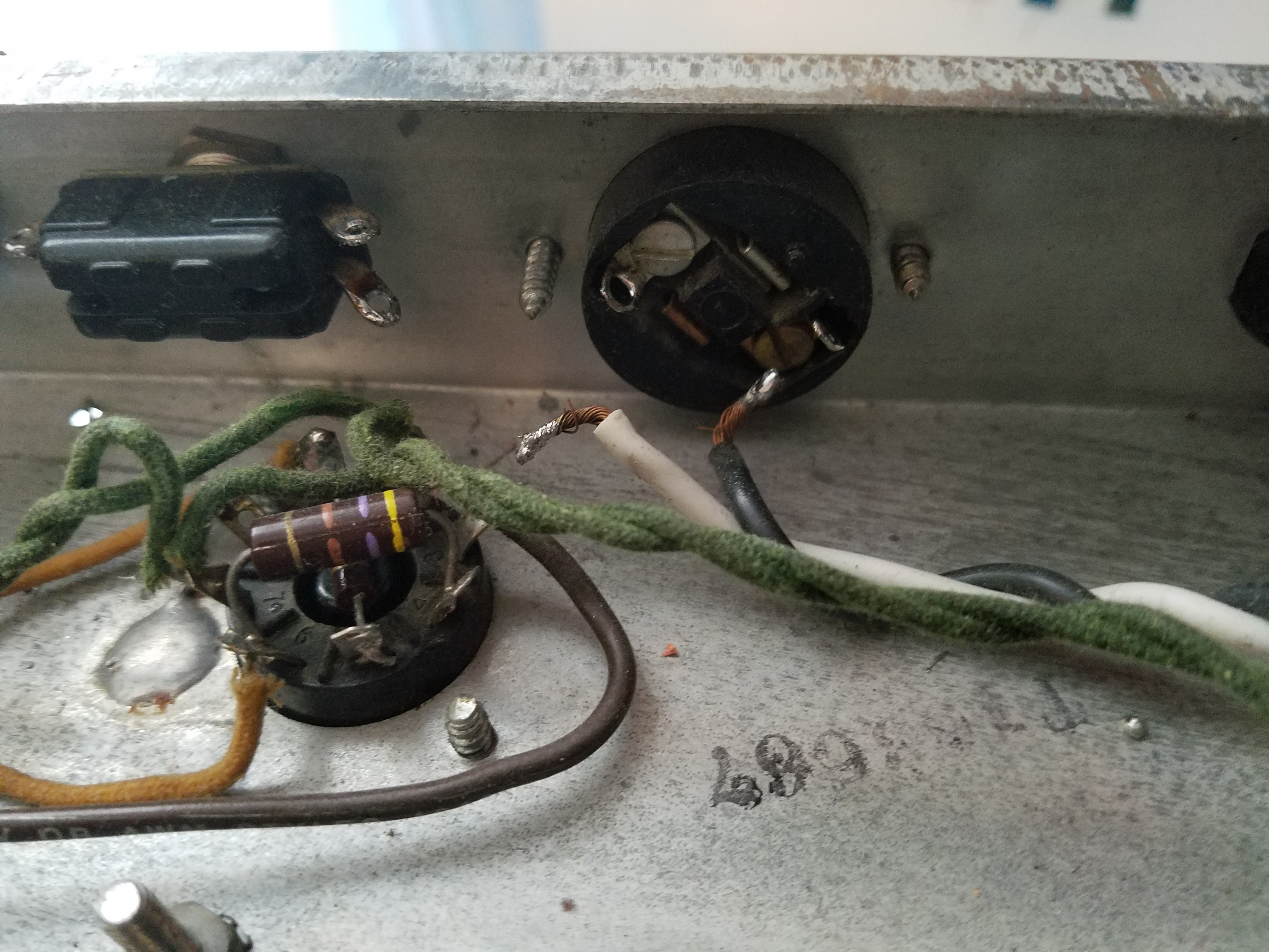 Next, in preparation for actually wiring things back up, I removed the black and white power wires from the two wire socket. I also cleaned out all the terminals of excess solder as you can see in the picture at the left. I used a solder removal tool, but a cheap alternative is to use a round toothpick while heating up the terminal. 😉
Finally, we get to start wiring things back up!! In the picture at the right,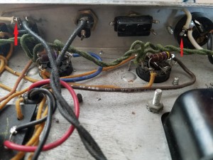 you will notice that I slightly changed the orientation a little bit. Now, the cloth covered wire is attached from the same direction as the white power cord. (It’s far easier to get both wires through the terminal in the same direction. I also marked the connection points with arrows.
Last connection!  In the picture at the left, you can see that I connected the black wire to the fuse holder. Now, we have the ground switch bypassed, and it can either be used, or replaced. I will be installing a switchable bass slope resistor in the next installment. I will remind you that solder ‘flows’ toward heat. 😉
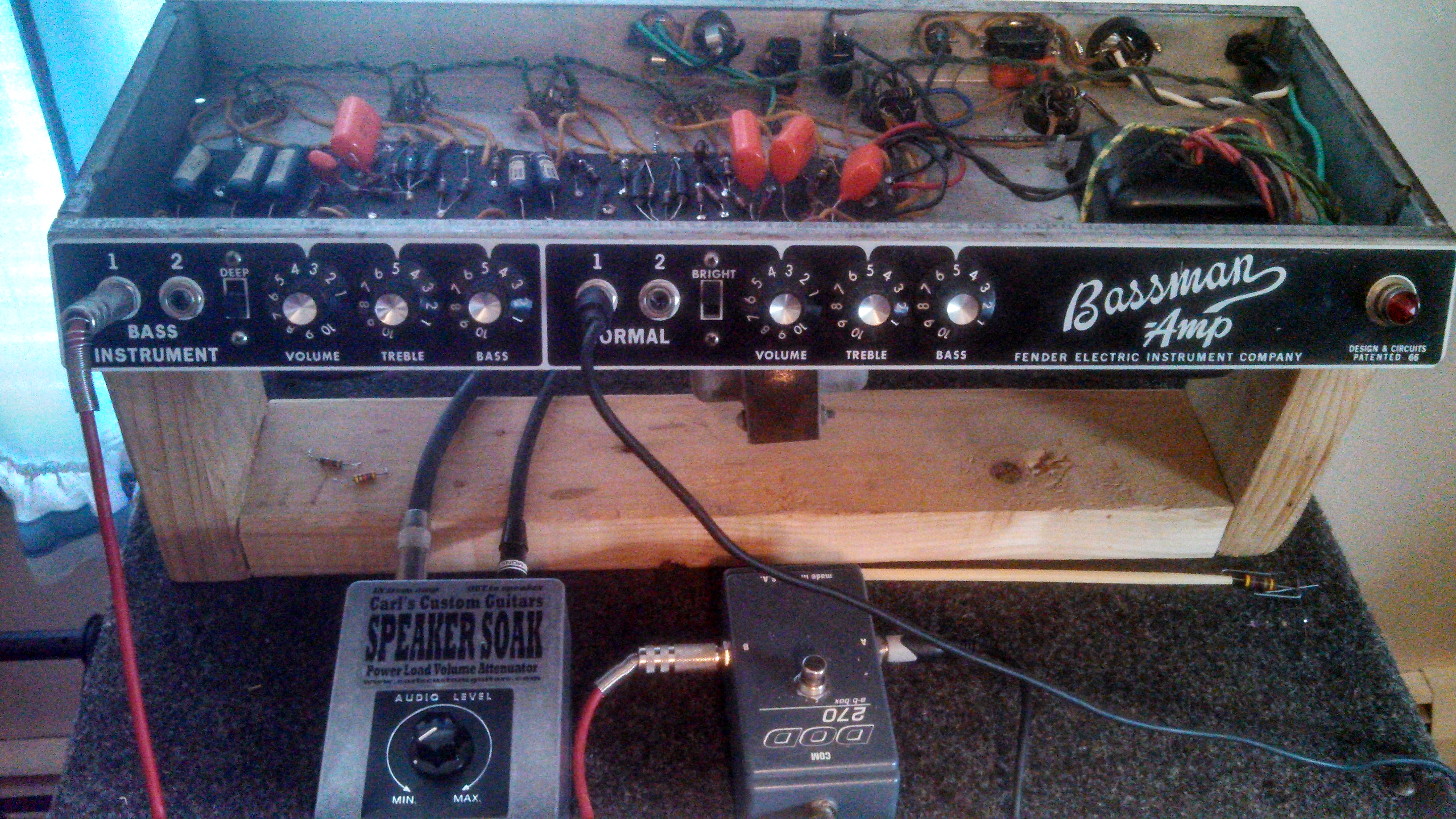
Last check!  If you haven’t a lot of experience in doing things like this, I will suggest that you use a DMM to check continuity of all the changes that you have made. Since I have 40 years experience, I simply plugged it in, and turned it on. You will notice the maintenance stand that I built in an earlier post. It makes it a lot easier to work on (and then test) your Bassman amp after you make changes. I suggest that you make one. Keep tuned for part 2. 😉