
There are some very simple circuits found in guitar amplifiers that we take for granted. But at the same time, do not understand. And there are other things thought to be “magic” , again, because they are not understood. (You can click on these images in order to see them better.)
This is an EASY article, brought on by my recent purchase of a 1967 Blackface Bassman amp that was modded to the first (and best) circuit, the AA864. –- Keep reading.
Two input jacks – found on Fenders and Marshalls (The Marshalls in question have four jacks, the Fenders usually have two, but the Bassman amps have two in each channel.)
Why is one high gain and the other low? And how does the whole thing work, what are these resistors doing?
Overall the two high and low gain jacks are a very good trick using switching jacks and as few parts as possible.
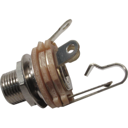
Jack #1, the high gain jack has a 1 meg (1,000,000 ohms) resistor wired across the jack from the hot tab to the ground tab, and the grounded lead of the resistors is bent back and soldered to the middle tab – the “switch.” The switch is grounded on jack #1.
These switching jacks have an extra “leaf” that is touching the hot, or “tip” connection of the jack – but only when nothing is plugged in – called a “normally closed” jack. This can be made to do all kinds of things.

Trick #1. In the case of the #1 jack, when you do not have your guitar plugged into the amp (either jack) the “switch” is closed – since it is grounded, the amp is turned off for low noise, and no chance of runaway.
The 1 meg resistor is the “grid load” resistor for the first tube stage of the amplifier. All tubes have to have a grid load resistance or they will not operate.
Instantly many of you are thinking, “what about the guitar pot, or the pickups, aren’t they a grid load?” Yes, they would be – but – if the guitar had active electronics, or had a capacitor in series with the output signal from the pickups, there may be no direct resistance from the guitar. It is better to be safe and have the resistor there.
Ok, more on the input jacks. The second jack has it’s switch soldered to the first jacks hot lead. Each jack has a 68k (usually) resistor from its hot lead, and they join together to make one lead to the tube stage.
These “series resistors” are sort of input buffers – to keep the amp from getting high level spikes from the instruments. Not totally necessary for the vintage guitars these amps were made for, but a real good idea for modern guitars with high output pickups, and in the old days, accordions!
Here is trick #2. Jack #2 has it’s switch soldered to Jack #1’s hot connection, and a 68k resistor on it’s hot lead – when the switch is closed – nothing plugged into jack #2, it’s 68k resistor is placed directly in parallel with Jack #1’s 68k resistor, for half the value, 34k. Less series resistance.
Trick #3. If you plug into jack #2 only, check out what happens. We already learned that if nothing is plugged into jack #1 the hot is shorted to ground via the switch – so now Jack #1 represents a direct ground connection.
The signal from jack #2 would pass through the 68k resistor, and at that point see the 68k resistor from Jack #1 with its other end grounded!! So the signal has 68k in series (more resistance, a lower signal level gets to the amp) and a 68k grid load resistor – much lower resistance than the 1 meg. A lower value of resistance to ground reduces the signal to the tube (again.) Check out the schematics to see what is going on. (Click on it to see it full-size)

The mysterious “interactive volume controls” on the Tweed Fenders (Bassman, Twin, Super, Bandmaster, Deluxe etc.) This is not some magic trick, or even an intentional feature – it is a minor design error.
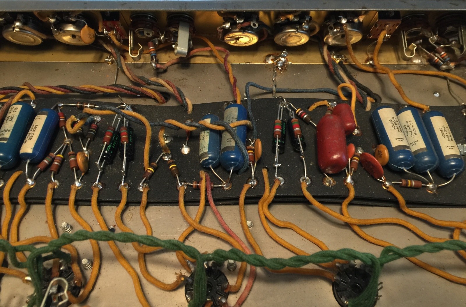
These amps have two volume controls each controlling one stage of a 12AX7 (7025) tube. They are very simple and economical circuits, only 5 parts per circuit. Each output comes from the volume control stage and passes through an “isolation” resistor – a resistor placed in the circuit to isolate the two volumes from each other, and at the same time to mix them for the next single input tube stage.
The “problem” or “feature” if you wish to call it that, is that the isolation resistors values are too low (270K on Tweed Bassman amps, and even lower – 220K on Blackface Bassman amps.) They do not isolate the stages from each other enough – one stage can still “see” the grid load resistance from the other. It appears to the channel you are plugged into, that there is another resistor in the circuit formed by the other unused volume control and it’s isolation resistor.
The real “magic” of it all is probably one of the absolute best “lessons” you can learn about vacuum tubes. You would guess that the best and loudest tone would be with the highest resistance, with the unused pot turned all the way up, but that isn’t so. It is somewhere near 5 or 6 (on old amps, a new amp may have different pot tapers and it could appear at different points.)
When you are turning the unused volume control you are “fine tuning” the grid load resistor to the next stage of the amp. An optimum (best sounding) value is not all the way up, but somewhere near the middle – the lesson? Tubes are NOT linear or mathematical devices – they do not respond to exact mathematical figures and have “hills and valleys” in their response – maximum performance can not be calculated directly – you have to hear it and you have to be aware that the “truth” may not be at some exact calculated place, but at some far more imprecise figure.