Fender Bassman AB165 Mod – NFB Mod

67 Bassman
67 Bassman

This is the second installment in the series of modifying a Fender Bassman amp with an AB165 circuit back to the more desireable AA864 (Leo Fender circuit).

69 SF Bassman
69 SF Bassman

These mods can also be applied to a huge amount of silverface ‘transitional’ amps.  The AB165 circuit was utilized in these amps until 1970.  For the most part, this mod and the bias adjust mod are the bulk of what’s necessary to ‘blackface’ an AB165 circuit.

DO NOT MODIFY A RARE LEO FENDER AA864 CIRCUIT!!  ALSO, DO NOT ATTEMPT TO WORK ON THESE AMPS UNLESS YOU KNOW WHAT YOU ARE DOING, AS THEY CONTAIN VOLTAGES THAT ARE LETHAL AND WILL KILL YOU!!!

This mod will focus on the absolutely horrible negative feedback loop that CBS added.  We will be removing it for the most part, restoring it back to AA864 specs.  We will also be discussing how we can tweek the frequency of the sound as well.
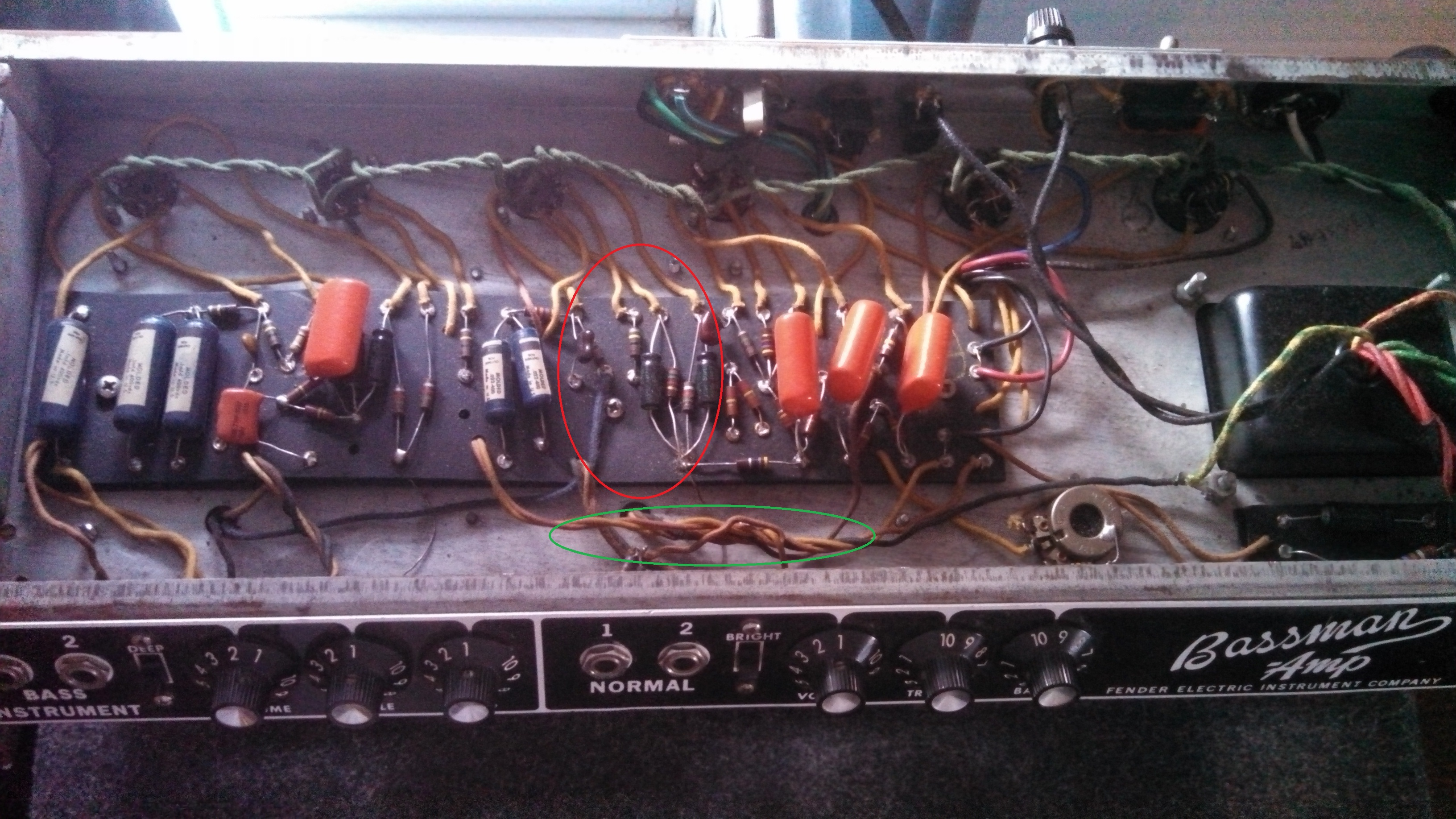
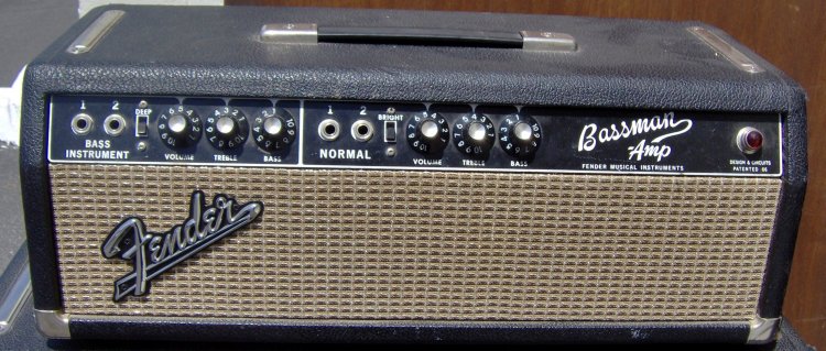
Let’s start off byBassman Innards Chassis NFB Mod taking a look at Jim’s 1966 AB165 Bassman for the areas we will be concerned with.  Marked in red are the main areas of the NFB loop.  Marked in yellow are the coupling caps from the phase inverter stage to the power tubes.  Marked in green is the part of the feedback that we will leave, but possibly tweek a little bit.  Why remove the power tubes’ NFB, you ask?  Because the end result of the NFB are a ‘neutered’ sound as well as lower volume and a ‘sweet spot’ of tube breakup at a higher volume setting.  So, by removing it, you will get: more volume at a given setting and the tubes will break up at a lower volume setting.  (You will get a little more white noise, but this should be able to be minimized by ‘adjusting’ the area in green a little bit.)

Here, we seeNFB Mod Schematic.2016.03.21RevA2 
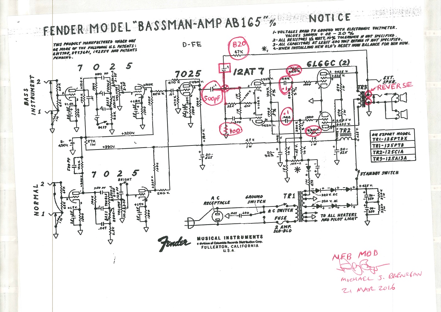
a copy of the AB165 schematic that I marked up with the changes.  (Don’t forget that you can click on it to see it full size.)  First thing is to remove the two 220K feedback resistors as well as to swap the two wires going to the speaker outputs and the feedback loop that is going to remain.  The two coupling caps from the phase inverter stage to the power tubes will be changed from .022 back to the AA864 values (.1).  Also, change the .1 coupling cap (from the output of the gain stage to the input of the PI) to the value used in the AA864 circuit, 500pf.  Also, in order to put the feedback loops back to Leo Fender specs, you need to replace the 47K resistor with an 820 Ohm one as well as remove the .1 cap (with the square around it).  You also need to move the feedback loop solder point to the 22K resistor.  This point is currently at ground, so you need to insert a 100 Ohm resistor to ground. NFB Mod Layout.20160321RevA2

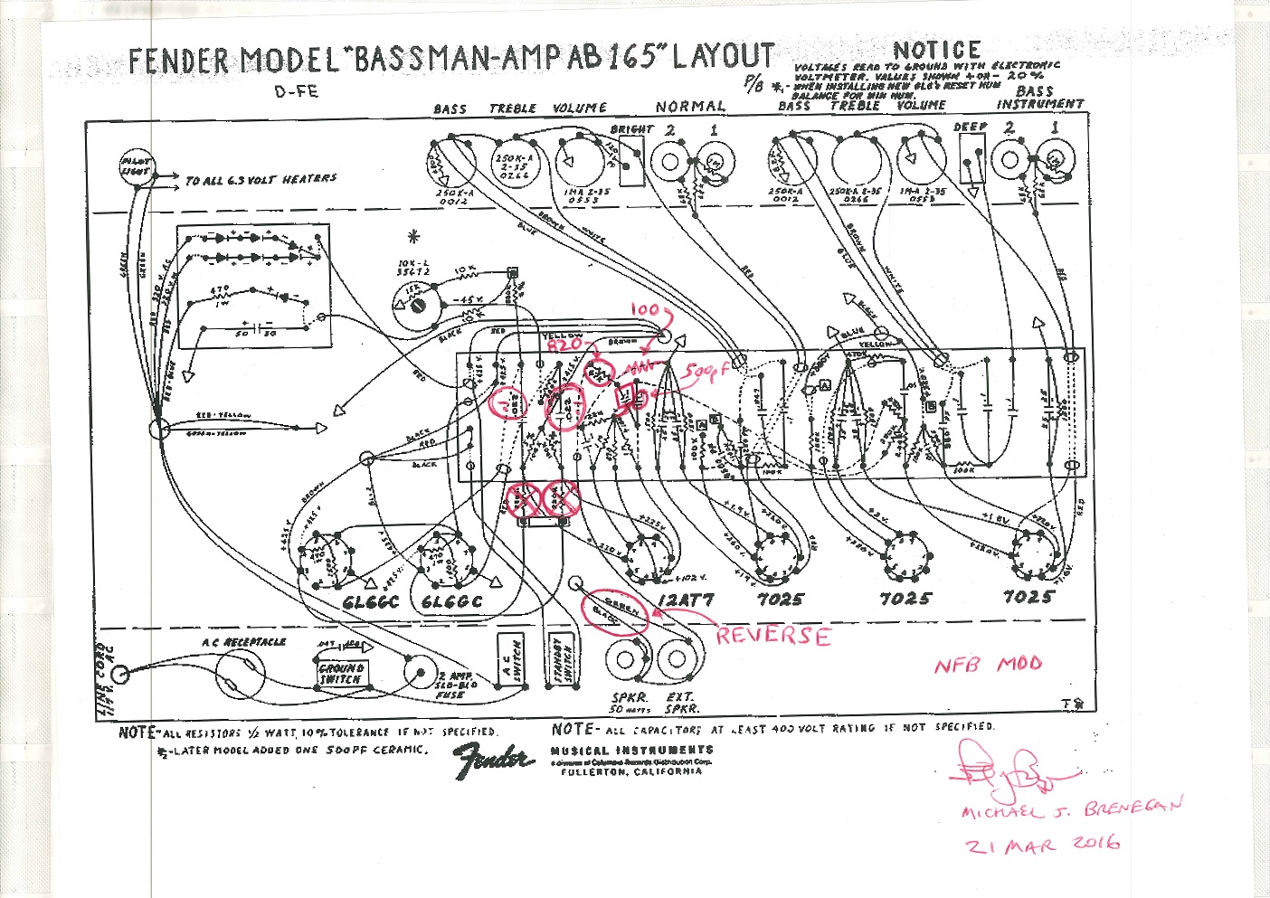
Here is the layout diagram for the NFB mod.  The cap (with the square around it) can be either taken out (to restore the loop to Leo Fender specs), or left in, or changed to a different value (to change the frequency response of the feedback).  For example, going to a .01 cap only allows the higher frequencies to pass (and cancel), getting rid of the harshness.  You can also change the 820 Ohm resistor to 1.5 K Ohm, reducing the amount of feedback felt, and allowing for a better tube breakup.

If you think this through carefully, you can make the cap ‘switchable’ using the ground switch, if you have bypassed it and removed the ‘death cap’.  Or, you could utilize the 1/4″ Ext Speaker jack (if you disconnect it), and make the cap and/or resistor switchable via a latching foot switch.

That conclude this segment.  This mod might not be for you if you want a calmer, mellower  Bassman.  This mod might be for you if you want an aggressive  Bassman with more bite and more volume and better break up at lower volumes, and the ability to ‘cut through’ the music.  😉

Next segment will look at tone shaping.

Fender Bassman AB165 Mod – Bias Adust

The Fender Bassman Blackface amp is arguably the most sought after tube amp.  However, it’s not bass guitar players that covet this amp, but guitar players.

66 Fender Bassman BF

The amp’s circuit underwent three changes in the Blackface era from 1964 through early 1967:  AA864, AA165 and AB165.  (The AB165 circuit was a product of CBS’ ownership of Fender, and continued to be used in the Silverface era from 1967 through 1970.)  The picture above is a 66 Bassman, with matching speaker cabinet.  If you are lucky enough to own this pair, you are fortunate indeed, but if you own just the amp, you most certainly own a treasure.  This series of blog posts will center on modifications to the

69 Bassman SF
69 Bassman SF

AB165 circuit, which is the most common one out there, and is contained in many Silverface Bassmans like the one pictured to the left.   The Silverface era lasted from 1967 until 1977, with the AB165 circuit being used until early 1970.  There were a half dozen other circuit variations in the SF amps, but many of these mods can be applied to their circuits as long as you carefully study them.  The AB165 circuit contained a couple good points, but more bad points.  CBS really got their hands into these circuits, and in a lot of respects ‘sterilized’ them.  These mods that I will go over carefully, are for the most part considered upgrades, and do not diminish the value of your amp.

DO NOT MODIFY A RARE LEO FENDER AA864 CIRCUIT!!  ALSO, DO NOT ATTEMPT TO WORK ON THESE AMPS UNLESS YOU KNOW WHAT YOU ARE DOING, AS THEY CONTAIN VOLTAGES THAT ARE LETHAL AND WILL KILL YOU!!!

That being said, there are a few things that you most probably should do right away, if your amp is not modified.  First, you should replace all the electrolytic filter caps under the doghouse with new electrolytics of the same value.  Second, you should REMOVE the ‘Death Cap’, which is wired across the ground switch.  Third, you should upgrade the power cord to a three wire power cord with ground.  Last, you should probably replace the ‘brown turd’ caps with Sprague ‘orange drops’ of the same values.

This first post in a series of Fender Bassman modifications will center on restoring the horrific mod that CBS did to the bias circuit, turning it into a ‘hum balance’ or ‘bias matching’ circuit.  It may have been more important in days gone by when power tubes weren’t ‘matched’ as they are presently, when you purchase new tubes.  When the tubes are matched, it’s more important to set the overall tube grid bias than it is to match what should already be matched.

Bias Circuit AB165
Bias Circuit AB165

Well, let’s get started.  In this picture of a friend’s 1966 Bassman, (Jim Geikler, you should recognize this, heh) you see the area of concern circled in red.  You can also see the ‘brown turd’ caps that I spoke of.  So, we shall restore this awful attempt at a bias adjust circuit to Leo Fender’s bias circuit.  In

Bias Adj Mod Schematic

this schematic,  you can see that I have removed the two 10K resistors attached to both sides of the bias adjust pot, as well as the 220K resistor that provided the ‘fixed’ bias to the grid of the lower power tube.  Then, the 220K Bias Adj Mod Layout

resistor is moved, so that it supplies adjustable bias to  BOTH power tube grids through both 220K resistors and the 1500 Ohm grid resistors.  This layout shows you how easy this change actually is.  Removing two components (the two 10K resistors), and moving

Bassman Bias Mod
Bassman Bias Mod

one end of the third component (the 220K resistor).  This picture shows the finished product.  I have circled the 220K resistor that was moved.  I hope that this was easy enough to follow along and you now have a true Leo Fender designed grid bias circuit.  (After this mod has been performed, you WILL need to measure and set the bias to the power tubes.)  Stay tuned, as our next installment will focus on getting rid of that awful CBS-designed negative feedback loop in the power tubes’ circuit to help reduce the sterility and increase the gain a bit.  😉

1967 Fender Bassman Hum Troubleshooting and Fix

I recently picked up a 1967 Fender Bassman amp from a guy in Florida.  Even though it sounded fairly nice…..

You can hear from the video above, that it has a nasty hum, even with no guitar plugged into it when turned up.  I really didn’t want to send it back, since it is in excellent shape and has been modified from the CBS AB165 circuit to the Leo Fender AA864 circuit, so my work on this amp will be fairly minimal.

*** Do NOT attempt this unless you are qualified to do so.  These amps have LETHAL voltages inside of them that can easily kill you and turn you to charcoal!  If you don’t know what you are doing, do yourself a favor and call an engineer! ***

The first step was to build an amp ‘stand’, so that I could remove the chassis from it’s cab and hook it up to a speaker so that I might trouble shoot it.  Bassman Amp standYou can see that here.  The measurements for the stand are cut from a standard 2 by 4 and the base is 18.25 inches and the sides are 7 inches and screwed onto the ends of the base.  You can also cut two 5.5 inch pieces that will make the stand narrower by setting one or both on the inside and using a rubber band to hold it or them in place.  (In case you wish to use this ‘stand’ on an amp chassis that might be narrower.  😉

The most common causes for that kind of hum can be found by either basic trouble shooting or a visual inspection.  First, to rule out the V3 tube that is on the guitar channel only, I swapped it with V1, the input tube of the bass channel.  No change.  So, next, I really spent a few good minutes inspecting the normal channel’s input stage circuitry, as you can see in this pic, if  you click on it, I have marked a couple areas that appear to be problematic. The areas I have circled on the board is Bassman main board problemswhere the Normal channel input tube’s circuitry is located, and has many suspect solder joints.  The bundle of wires that I circled, is of interest because it contains the wiring coming from the input jack as well as the wiring to/from the output transformer, and is a perfect example of very poor ‘lead dress’.

I also took a couple voltage Bassman normal input stagemeasurements, which I felt entirely unnecessary, and just served to prove that V3 (Guitar channel input triode) was operating properly.  The measurements were: pin 1: 238V, pin 3: 1.9V, pin 6: 221V, and pin 8: 1.6V (all voltages are volts DC).  This tube stage is operating fine, so the hum must be coming from the input jacks, or the tone stack, both of which had visually detected problems.

Below is a video that absolutely proves that your first and best bit of troubleshooting is your visual checks.  😉

Still a small amount of work to do…..  Clean up the sloppy soldering on the board (may as well go over the whole amp, resoldering any suspect joints) and also remove that ‘death’ cap, but now, this amp sounds really nice and LOUD!

Keep your eyes peeled here, as I fully intend to go over some Bassman modifications that will get some great results when applied to an AB165 blackface OR silverface amp.  😉